ILFP
ILFP Product Support
PALFINGER has built a reputation as a market leader in technical support and lifetime product service. This also rings true with the ILFP liftgate. Whether you need help through our service network or our dedicated Technical Service Team, PALFINGER will ensure your equipment stays up and running. PALFINGER products feature heavy-duty, hardened and corrosion-protected pins with low-maintenance greaseable bushings. The power packs are equipped with thermo-switch-protected motors and extra heavy-duty solenoids.

Product Specific troubleshooting
Keeping your equipment up and on the road is priority number one. When using our troubleshooting guide with assistance from our dedicated technical service team, you can feel confident that your liftgate will be repaired correctly and in a timely fashion.
NOTE: Always use a digital voltmeter when checking voltage to determine if you have sufficient power to operate the liftgate.
Before doing 10 -10 test:
1. Shut off the truck engine
2. Unhook the charge coil from tractor
3. Shut off the battery charger
4. Disconnect any outside battery source
Confirming battery voltage with 10 -10 test:
- Using a multimeter, set on DC voltage
- Attach the volt meter negative to the negative post on motor
- Attach the volt meter positive to the positive post on motor
- Using the lift switch, raise the platform to bed level
- Keeping the switch activated, deadhead the motor
- Keep the switch activated for ten (10) seconds and observe the multimeter reading
- Ten (10) volts for ten (10) seconds is the desired result
- If the reading is less than eight (8) volts, the batteries are low and need to be charged
- Retest after charging
- Replace batteries and check all connections and grounds if you cannot get 10-10
Liftgate Not Working
| Do you hear solenoids clicking | Hear no solenoids clicking |
|---|---|
|
Bad solenoid valve |
Motor not running
- Jump across large posts on motor solenoid
- If the motor runs, test for incoming signal on the small terminal and ground on the other small terminal
- Test the thermo switch in the motor for continuity if the signals are good, replace the motor solenoid
- Jump across large posts on motor solenoid
- If the motor does not run, jump the motor directly with jumper cables from a separate good battery
- If the motor is not running, tap on the motor; if the motor runs, the brushes are bad
- If the motor runs, check the motor ground and power to the motor solenoid
Truck: Turn on the cab switch
Trailer: Turn on the switch at the liftgate
- Check the fuse, and circuit breaker at the battery
- Check fuses at the PC board
- Unplug these 3 connections on the PC board:
- J-31 Hand Control
- J-3 Warning Lights
- J-41 x 2 B-13 and B-15 sensors
- M control—check fault codes
- Clear the code: unplug J-11 and J-1 then plug back in
- Remove the J-30 plug, confirm #4 pin has voltage, jump #4 to the next 4 pins to get up, down, tilt down, tilt up, note last pin is ground do not touch with the jumper on the J-4 pin
| Fault Codes | |
|---|---|
| #1 | Liftgate On |
| #0 | Liftgate Off |
| #2 | Low Voltage |
| #8 | Short |
| #5 | B-15 Problem |
| #3 | B-13 Problem |
Emergency Operation: #E mode—emergency by-pass of sensors
- Turn and hold both down and tilt down knobs for 10 seconds until E code is shown
- Operate liftgate in E mode
- To reset turn the liftgate OFF and then ON
Liftgate Not Lifting
- Motor not running: see section above
Liftgate not lowering
- S-1 and S-2 valves on lift cylinders not opening
Liftgate not tilting up
- S-5 valve on the motor not energizing along with the motor
Liftgate not tilting down
- S-3 and S-4 valves on lift cylinders not opening
Liftgate not lifting load
- First, add a 12-volt power supply direct to the batteries
- Second, move the 12-volt power supply directly to the motor solenoid and ground it on the motor
- Adjust PSI to 3000 PSI
- Change hydraulic fluid to fluid ISO 32
Foot Controls Troubleshooting
First, check that you have power on the Inner E terminal on J1 or J1A to power the foot controls circuit

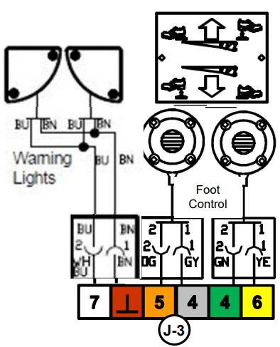
| J-3 Plug Pin Functions | |
|---|---|
| 5 Pin | UP—Orange Wire |
| 4 Pin | Hot—Grey and Green Wires |
| 6 Pin | DOWN—Yellow Wire |
| 12V+ | Reading at Both 4 Pins |
| 7 Pin | Warning Lights—White Wire |
| Ground Pin | Brown Wire |
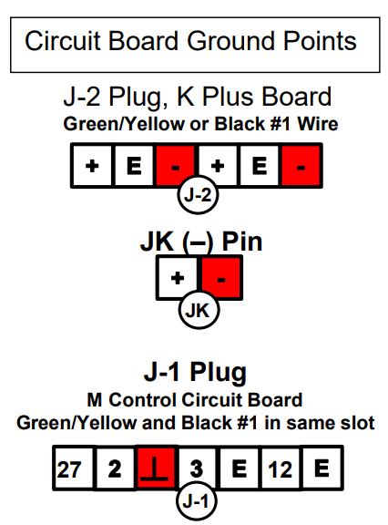
When checking the voltage on the circuit board, ALWAYS Ground to the circuit board.
Diagnostics and Troubleshooting Foot Controls
Activate the Foot Controls in the sequence depicted on the plate riveted to the platform.
If activating the UP function, check the voltage at the 5 Pin; the reading should be 10V or more.
If activating the DOWN function, check the voltage at the 6 Pin; the reading should be 10V or more.
If activating the UP or DOWN function by jumping at the J-3 Plug, both 4 and 5 or 6 Pins must have power from the 4 Pin as an example: To activate the UP function, jump from 4 Pin (next to the 5 Pin) to 5 Pin, then within 3 seconds jump to 6 Pin while still having the jumper on the 4 and 5 Pins. Reverse the process for the DOWN function using the 4 Pin next to the 6 Pin. Inspect cables for continuity, pinches, insulation compromise, and other conditions that could cause a short in the circuit if the liftgate won't function. Replace foot switch(s) if defects are found.
Remember, proper voltage is key for the correct function of this feature. Other components are also being activated and require proper voltage. Low voltage may cause one function to not properly respond, causing the liftgate not to operate as desired.