Knuckle Boom
PK 76002 EH High Performance
- Go back
- Home
- Products
- Knuckle Boom Cranes
- Models
- PK 76002 EH High Performance
PK 76002 EH High Performance
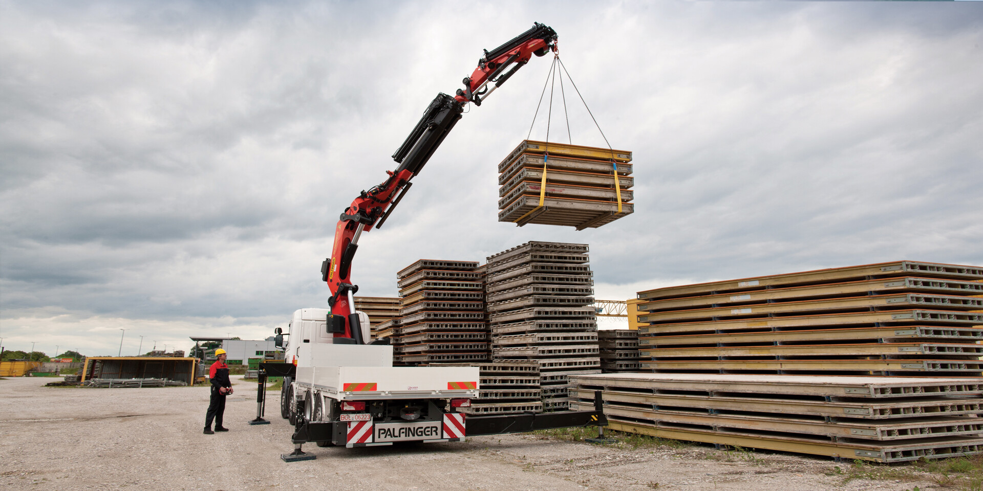
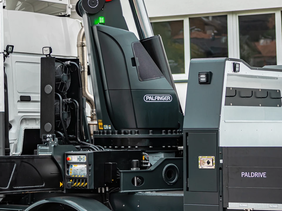
Functional Design. For service friendliness, best appearance and high value retention.
- Additional applications due to Power Link Plus
- Maximum utilisation of the working range due to HPSC
- Practical and attractive due to Functional Design
- More lifting power due to E-HPLS

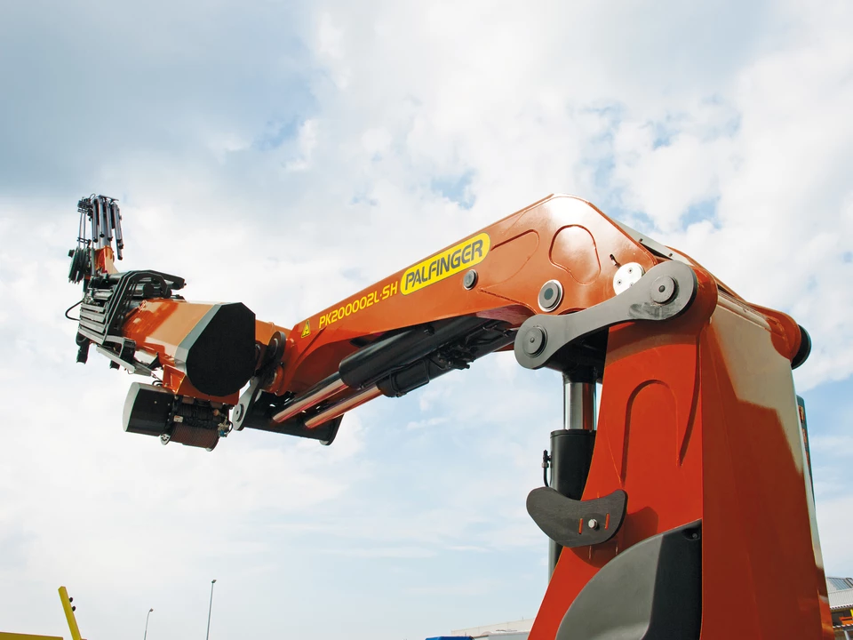
High Power Lifting System
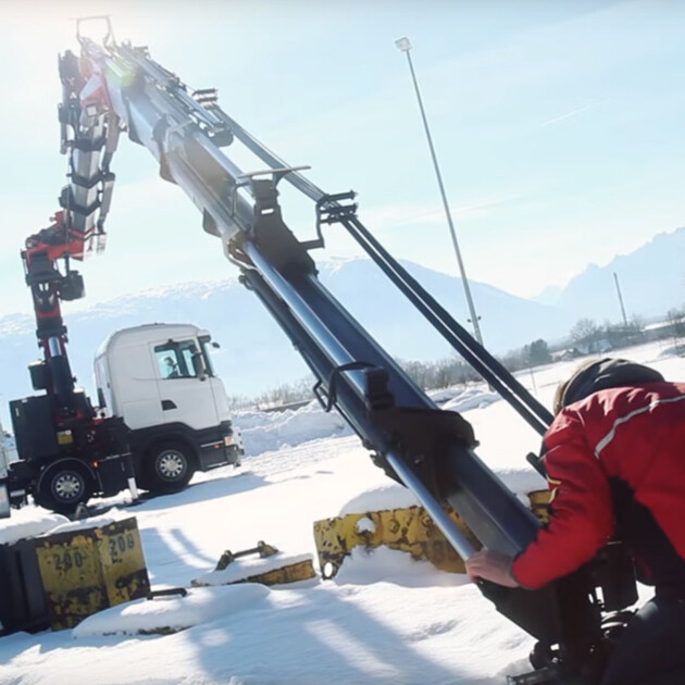
The PALFINGER High Power Lifting System (E-HPLS, A-HPLS or S-HPLS) increases the capacity of the crane by up to 15% while reducing working speed. E-HPLS can be activated manually for the occasional manipulation of very heavy loads. A-HPLS as well as S-HPLS are activated fully automatically. There is continuous activation depending on the power required.
Continuous Slewing System
The PALFINGER Continuous Slewing Mechanism permits an unrestricted radius of action. The crane is rotated or 'slewed' using a gear box and hydraulic motor instead of a rack and pinion system. All endless slewing mechanisms come as standard with a high quality roller ball bearing.
Power Link Plus
The PALFINGER Power Link Plus system is a double linkage system with a linkage on the knuckle boom and a linkage between the main boom and crane column. With the 15 degree reverse linkage system, reaching through low door openings or working inside buildings is no problem.
Experience the product features
KTL
PRODUCT FEATURES
The right surface treatment is the foundation for durable and long-lasting surface protection. The components pass through the priming and painting process stages fully automatically. Through this innovative technology for surface coating, PALFINGER creates a quality standard that is usually only found in the automobile industry.
HOW IT WORKS
1. The crane components are cleaned of all impurities by means of cut steel shot blasting.
2. The components are degreased, rinsed, activated and coated with zinc phosphating in the individual immersion tanks.
3. After two additional rinsing processes, the surfaces are passivated as well as rinsed with ultra-pure water.
4. The electrostatic cathodic dip painting follows by immersing the crane components completely in the paint.
5. Excess paint is washed off in two additional operations with an ultra-filtration rinse.
6. Afterwards, the paint is cured at a temperature of 115 degrees for 1.5 hours.
7. At the end, the crane components are given a water-soluble, environmentally friendly two-component finish coat of paint by a painting robot.
HPSC
PRODUCT FEATURES
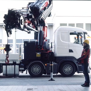
The High Performance Stability Control (HPSC) is a fully proportional system for monitoring the stability of the crane vehicle. Sensors for proportional path measurement in the stabilizer supports permit completely variable support positioning. Hence, the permissible, safe working range can be calculated for any support situation.
HOW IT WORKS
The HPSC system calculates the permissible working range for any slewing angle of the boom system and for any support situation. The position of the stabilizer support is detected by means of a cable extension transducer or magnetostrictive position sensor. Based on the intelligent calculation algorithm developed by PALFINGER, it works more efficiently than comparable systems that are available in the market.
* Optional feature/country-specific-equipment
AOS
PRODUCT FEATURES
The patented PALFINGER "AOS" oscillation suppression system cancels out vibrations and blows that occur during crane operation. Any "post-oscillation" is prevented through rapid braking or load changes. The result is a decisive increase to safety in crane operation for employees, the load and building.
HOW IT WORKS
The electronics receive signals from pressure sensors on both sides of the elevating cylinder and interpret them as arm vibrations. The signals for the counter-movement of the elevating cylinder are handled by the control valve. The incurred vibration can be cancelled through the exactly determined frequency and wavelength. The result is damping of the arm to just one or two short vibrations so that the arm comes to an immediate standstill. Patent granted
* Optional features/country-specific-equipment
Radio Remote Control
PRODUCT FEATURES
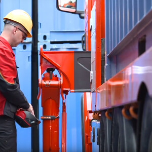
Today, radio remote controls are often considered to be standard equipment when it comes to modern loader cranes. PALFINGER radio remote controls are equipped with a choice of a linear lever or cross lever and provide the greatest possible comfort of the operator. For cranes with PALTRONIC an LCD graphic display or 4.1 inch TFT- colour display informs the crane operator of the different operating conditions.
HOW IT WORKS
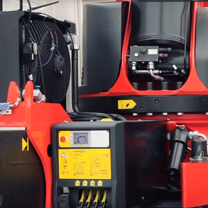
The remote control console (transmitter) is responsible for transmitting the commands made on the levers to the receiver. The receiver forwards the signals to the electronics, which convert them into crane movements by means of hydraulic control valves.
- Technical data U.S. Units
- Technical Data Metric
- Lifting Capacities U.S. Units
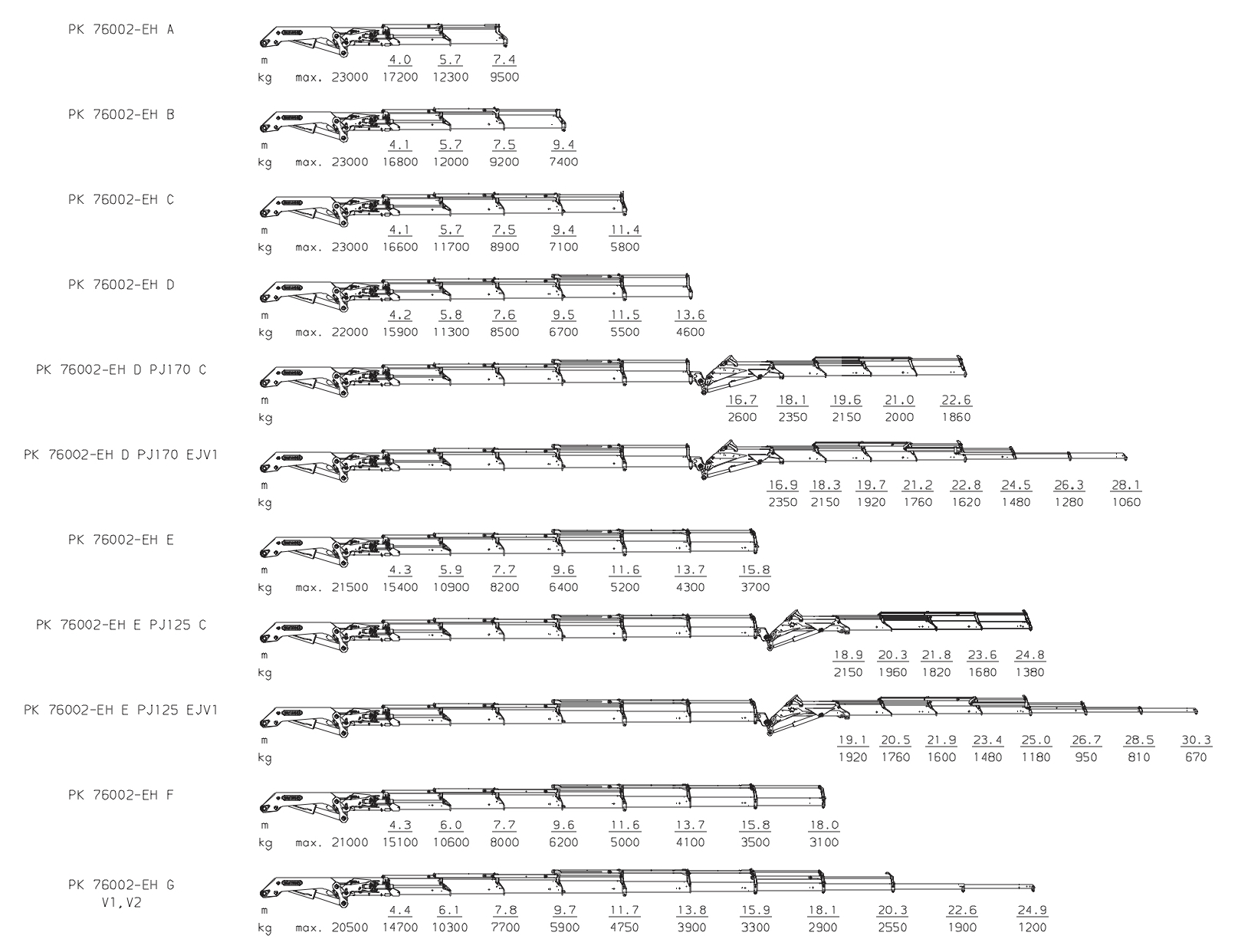
- Lifting Capacities Metric
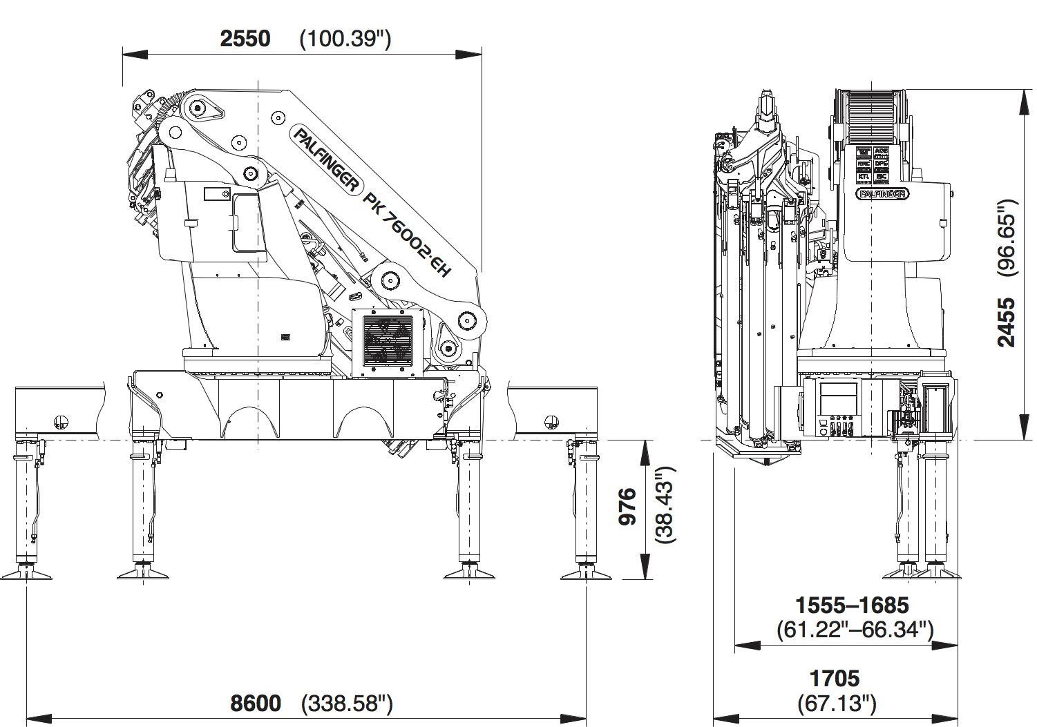
| Max. lifting moment | 511515.0 ft lbs |
| Max. lifting capacity | 50,710 lbs. |
| Max. hydraulic outreach | 66' 11" |
| Max. manual outreach | 82' 4" |
| Max. outreach (with fly jib) | 100" 1" |
| Slewing angle | ∞ |
| Slewing torque with 1 gear | 32557.0 ft lbs |
| Slewing torque with 2 gears | 50640.0 ft lbs |
| Stabilizer spread (std) | 28' 3" |
| Fitting space required (std) | 66.34" |
| Width folded | 100.39" |
| Max. operating pressure | 5075 psi |
| Pump capacity | 21.1 - 26.4 gpm |
| Dead weight (std) | 13029 lbs |
Cranes shown in the leaflet are partially optional equipped and do not always correspond to the standard version.
Country-specific regulations must be observed. Dimensions may vary. Subject to technical changes, errors and translation mistakes.
| Max. lifting moment | 71.6 mt |
| Max. lifting capacity | 23000 kg |
| Max. hydraulic outreach | 20.4 m |
| Max. manual outreach | 25.1 m |
| Max. outreach (with fly jib) | 30.5 m |
| Slewing angle | ∞ |
| Slewing torque with 1 gear | 4.5 mt |
| Slewing torque with 2 gears | 7.0 mt |
| Stabilizer spread (std) | 8.6 m |
| Fitting space required (std) | 1.71 m |
| Width folded | 2.55 m |
| Max. operating pressure | 350 bar |
| Pump capacity | 80 - 100 l/min |
| Dead weight (std) | 5910 kg |
Cranes shown in the leaflet are partially optional equipped and do not always correspond to the standard version.
Country-specific regulations must be observed. Dimensions may vary. Subject to technical changes, errors and translation mistakes.
|
(ft_lbs) |
|
(°) |
(ft_lbs) |
(psi) |
(gpm) |
(lbs) |
(inch) |
Crane Width (inch) |
(inch) |
|
|---|---|---|---|---|---|---|---|---|---|---|
| A | 511515.0 | - | ∞ | 32560 / 50640 | 5075.0 | 21.1 - 26.4 | 13029 | 96.65 | 100.39 | 61.22 |
| B | 497768.0 | - | ∞ | 32560 / 50640 | 5075.0 | 21.1 - 26.4 | 13779 | 96.65 | 100.39 | 61.22 |
| C | 486192.0 | - | ∞ | 32560 / 50640 | 5075.0 | 21.1 - 26.4 | 14506 | 96.65 | 100.39 | 61.22 |
| D | 479681.0 | - | ∞ | 50640 | 5075.0 | 21.1 - 26.4 | 15520 | 96.65 | 100.39 | 61.22 |
| E | 474616.0 | - | ∞ | 50640 | 5075.0 | 21.1 - 26.4 | 16116 | 96.65 | 100.39 | 61.22 |
| F | 470275.0 | - | ∞ | 50640 | 5075.0 | 21.1 - 26.4 | 16601 | 96.65 | 100.39 | 66.34 |
| G | 466658.0 | 82' 4" | ∞ | 50640 | 5075.0 | 21.1 - 26.4 | 17041 | 96.65 | 100.39 | 66.34 |
|
(mt) |
(m) |
(°) |
(mt) |
(MPa) |
(l/min) |
(kg) |
(mm) |
(mm) |
(mm) |
|
|---|---|---|---|---|---|---|---|---|---|---|
| A | 69.1 | 7.6 | ∞ | 4.5 / 7.0 | 35.0 | 80-100 | 5908 | 2455 | 2550 | 1555 |
| B | 68.2 | 9.5 | ∞ | 4.5 / 7.0 | 35.0 | 80-100 | 6246 | 2455 | 2550 | 1555 |
| C | 67.2 | 11.5 | ∞ | 4.5 / 7.0 | 35.0 | 80-100 | 6580 | 2455 | 2550 | 1555 |
| D | 66.3 | 13.7 | ∞ | 7.0 | 35.0 | 80-100 | 7040 | 2455 | 2550 | 1555 |
| E | 65.6 | 15.9 | ∞ | 7.0 | 35.0 | 80-100 | 7310 | 2455 | 2550 | 1555 |
| F | 65.0 | 18.1 | ∞ | 7.0 | 35.0 | 80-100 | 7730 | 2455 | 2550 | 1685 |
| G | 64.5 | 20.4 | ∞ | 7.0 | 35.0 | 80-100 | 7730 | 2455 | 2550 | 1685 |
The outreaches stated are with a boom angle of 20° and are therefore not the maximum. When using mechanical boom extensions, the loads shown on the charts need to be reduced by the weight of these extensions.
PALFINGER SERVICES
Brochures
You are currently on the PALFINGER United States page which shows the corresponding product assortment. We noticed that you come from a different location. Do you want to change to another PALFINGER country page?
